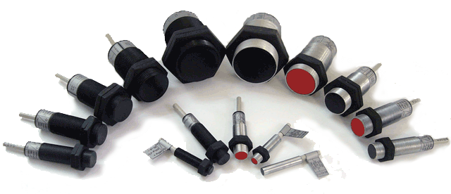
Optoelectronic and photoelectric sensors Characteristics
The optoelectronic and photoelectric sensors and switches are used as electronic equipment for automation of production processes. Brief information is given underneath about their functions, designation, characteristics and electrical circuits of connection.
Operating principle
The photoelectric sensors and switches are used as electronic equipment for automation of production processes. They are widely used in various areas of industry due to the contactless switching of the electrical circuits, in which included. There are various types of photoelectric and optoelectronic sensors depending on the principle of operation. Underneath is given information about their function, operating conditions, type designation, technical characteristics and electrical circuits of connection.
Types of photoelectric sensors
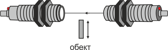
Thru-beam sensor
It is a system of two housings (transmitter and receiver) situated one against the other and connected by a modulated infrared ray of light. When an object passes between the transmitter and the receiver, the ray of light becomes disconnected and the output of the receiver change state
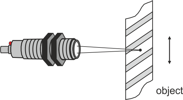
Diffuse sensor
It consists of one housing, in which transmitter and receiver are situated. The sensor emits modulated ray of light, which is reflected by the passing (coming near) object and returns back to the sensor. In such case the output of the switch change state. It is intended for detection on different objects of the automatics.
Mark sensor
It consists of one housing, in which transmitter and receiver are situated. They serve to register coloured mark stripes inflicted on object, that is passing in a strictly fixed zone (of 10÷20mm) in front of the active surface of the sensor. The width of mark stripes can not been less 3 mm.
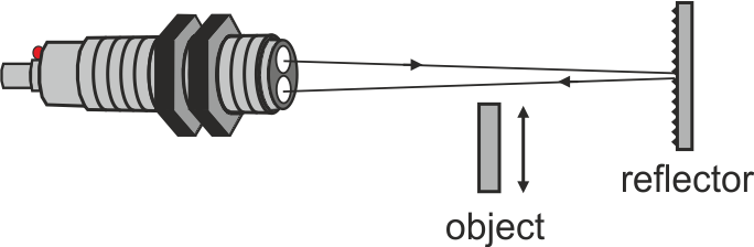
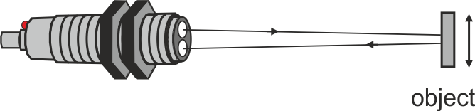
Retro-reflective sensor
It consists of one housing, in which transmitter and receiver are situated. The sensor emits infrared modulated ray of light which reflects on a reflector and returns back to the sensor. When an object passes between the sensor and the reflector, the ray of light becomes disconnected and the output of the sensor change state.
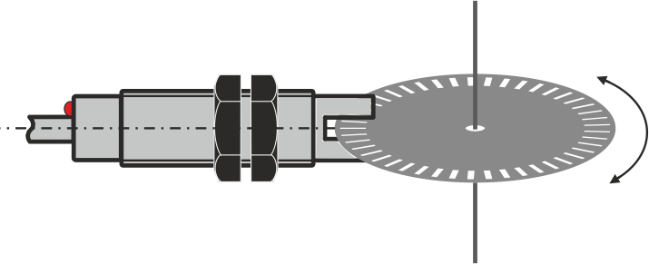
Fork sensor
It acts on the principle of emitting and receiving non-modulated ray of light in infrared area of the spectrum. They are used for measuring cycles of shafts etc. They have good sharing ability (0,5mm).
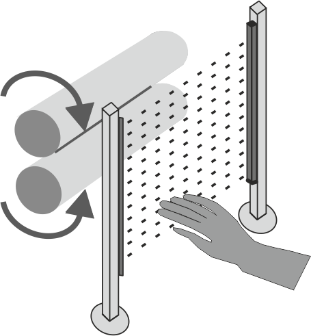
Safety light curtain
The specialized product is used to protect the machines and other moving elements from accidental interventions and to protect the machine operator from injuries.
Purpose and areas of application
The presented photoelectric sensors serve for switching direct current and alternating current electric circuits. Their principle of action consists in the emitting and receiving ray of light in infrared or visible area of the spectrum. The sensors are activated by interruption or reflection of the light rays when passing an object. They are used to automate production processes in the textile, packaging, bottling and other industries.
Conditions of exploitation
Photoelectric switches are not to be used in places where high level of water-vapour, thick fog, aggressive gases, splashes of oil, strong vibration could occur and also in dusty environment. The receiving part must not be influenced directly by the sun rays or other powerful light transmitters. The joining cable has not to be close to powerful electric circuits.
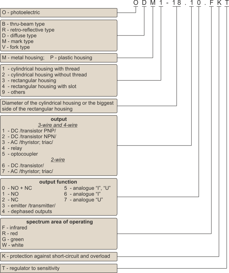
Type designation of optoelectronic sensors
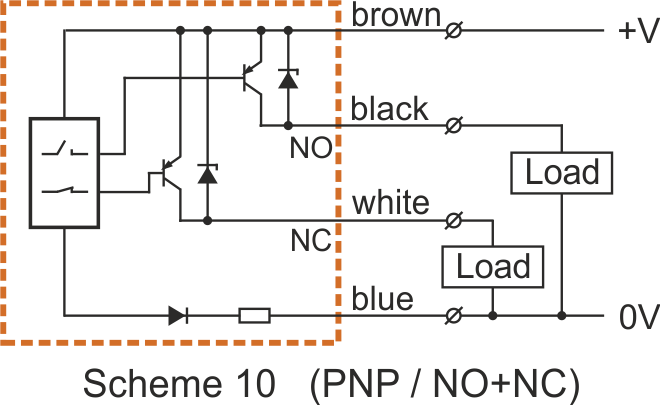
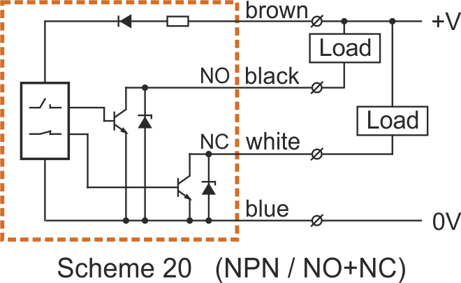
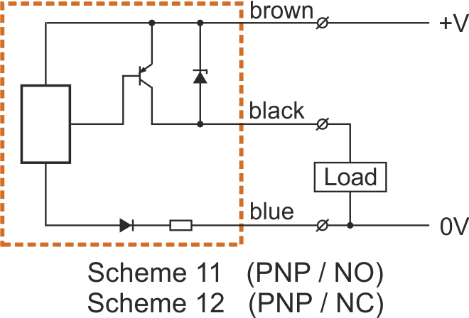
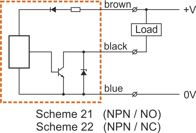
Electrical connection circuits of 3-wire and 4-wire direct current sensors, DC
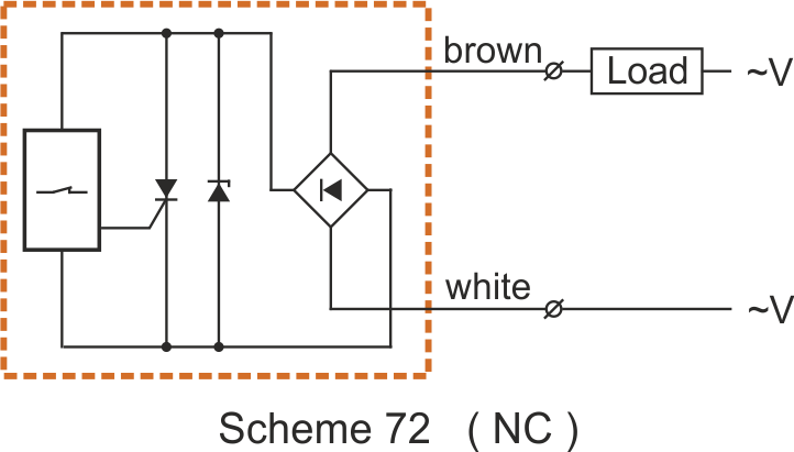
Electrical connection circuits of sensors of 2-wire alternating current, AC

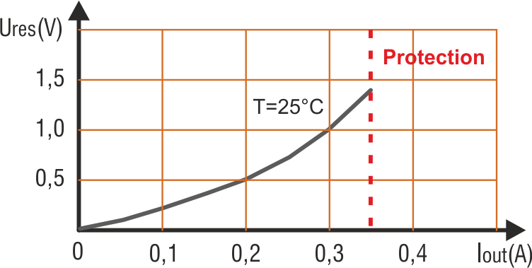
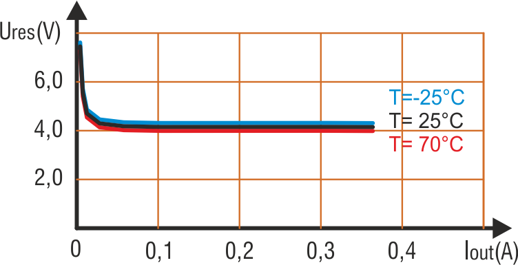
Output characteristic /residual voltage/
Features of connecting a capacitive load to DC sensors that have pulse protection against current overload
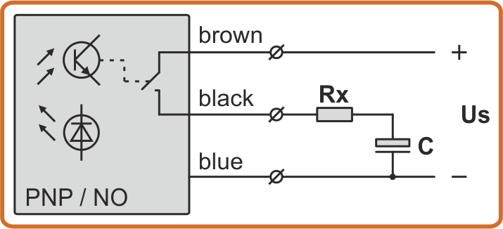
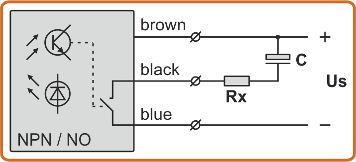
When connecting a capacitive load to the output of the sensors that have pulse protection against short circuit, it is necessary to connected in series a resistor Rx, which limits the current when initially charging the load capacitor C. Rx is added if capacitor C is larger than 100nF.
Rx = Us / 0,5 (Rx = 20Ω ... 60Ω)